Darrell Harmon's Single
Board Computer Project

About
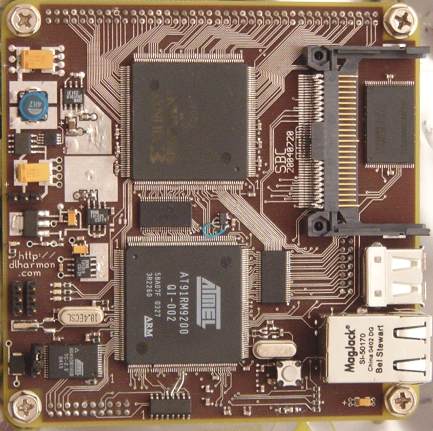
The SBC was designed for data acquistion applications, but can be used
in many other ways. I plan to build a digital scope module when I am
done with the SBC. The fpga is intended to allow for interfacing with
user created expansion boards. There is an 80 pin 2mm header with about
65 FPGA IO connected to it. A 50 pin memory interface connector exists
in version 20040720, but may not be included in the future. A third
connector provides power input, serial ports and SPI. In addition to
these expansion board connectors on the bottom side, there are serial
and power headers on top for testing the board independent of an
expansion board.
Features
Atmel AT91RM9200 microcontroller - ARM920T core, MMU, 208PQFP
Xilinx XC3S200 FPGA (Also supports XC3S400)
32MB SDRAM connected to AT91RM9200
32MB SDRAM connected to FPGA
64MB NAND Flash
Compact Flash Socket
2MB Atmel Serial Data Flash for bootloader and kernel
10/100 Ethernet
12Mb/s USB
2 Serial ports
6-14VDC power input
PCB
100x100mm (4x4 inches)
4 Layer
SMD on both sides
All parts on bottom are thin
Software used for schematics, board layout:
Downloads
WARNING: these files do not work as is. See the errata section.
PDF version of schematic (103K)
sbc.pdf
gschem and PCB files (114K)
sbc.tar.gz
bootloader and linux patches coming soon
Progress
8/18/2004 Successfully Booted Linux2.4.26-vrs1 with USB root. No CF,
ethernet, NAND flash, FPGA support yet.
7/20/2004 Completed board layout, ordered board from PCBExpress
2/1/2004 Started drawing schematics, researching parts
Errata for 20040720 board
DBGU serial port miswired. The AT91RM9200 schematic symbol is wrong.
Both SOT23-5 packages have wrong pinout. Need to create correct
footprints to replace the ones that came with PCB
FPGA oscillator pads are mirrored on the board. Fix footprint.
Crystals are bigger than the symbol - capacitors are underneath their
edges. Create more room in next revision.
Not all systems have been tested yet so there may be more.
Copyright Info:
I am releasing the hardware design into the public domain. You are free
to use it however you choose, but I would prefer that you make
schematics available as I have. All of the software is licensed under
the GNU GPL. See the COPYING file included with the source for more
info. I do not guarantee the design of the hardware or software to be
free of flaws. You are responsible for ensuring that it is suitable for
your application.
Related:
Last updated 8/20/04

